Overview
This blog is an extension of Developing Azure IoT Edge-Part I. Picking up from the Conclusion section from the Part I, the goals for this blog are to explore following objectives.
- Exploring SensorTag capabilities
- Providing clarity on the telemetry data by dissecting the IoT Edge code base.
- Connecting this telemetry output to do Hot Path/Warm Path/Cold Path analytics.
- Connecting additional SensorTags to the same Raspberry Pi IoT Edge Gateway
Exploring SensorTag Capabilities
Before we dive in to the telemetry data, lets first take look at the Sensor device itself to better understand what we are ready from it. My SensorTag model number is CC2650. This sensor has quite a punch to the list of sensors it has!
10 low-power MEMS sensors. Imagine all the interesting IoT features you could implement with this cost effective tiny sensor!
- light
- digital microphone
- magnetic sensor
- humidity
- pressure
- accelerometer
- gyroscope
- magnetometer
- object temperature (Make note of this)
- ambient temperature (Make note of this)

Understanding the Telemetry Data from IoT Edge
From the output of running the IoT Edge in the Pi terminal, you see below output under column Telemetry Data. Lets understand how is this configured and where is this data coming from and what they meant.
Lets explore following C code base which is responsible for the above display output of the telemetry. Refer to https://github.com/Azure/iot-edge/blob/d2c251d76a231eff3af4ffc4b854031dc9cacdde/samples/ble_gateway/ble_printer/src/ble_printer.c
For each configuration GATT UUIDs , in your configuration file, it is configured to read all the first 7 parameters one time and ready the Temperature every 1 second, which is what the telemetry output you see.
Configuration From gateway_sample.json | GATT Characteristic IDs From the ble_printer.c | Telemetry Data From the IoT Edge run |  |  | ![clip_image001[9]](https://blogger.googleusercontent.com/img/b/R29vZ2xl/AVvXsEh7zmKfpSbQpshvEfTzi0oZt48lxiruNSSQCx_6paiRRXUQfqSOGczztrM3X9Wjqbi6FMxOFYtYhNz790ZmZohPo5KHMcczGTOZJGwe-1VfOBcxBFSjoq_iJekkA2cgAlOpkF7I9PcekdWj//?imgmax=800 "clip_image001[9]")
| | |
| |
From the temperature telemetry, displayed as raw Ambient temperature read from the IR sensor, and raw Object temperature.
Understanding the Telemetry Data from monitor-events
Below is the iothub-explorer tool running under the monitor-events mode and displaying each messages received from the connected devices (This is referenced as D2C messages). What you see from each D2C message is BLE device Index, timestamp, the UUID and source, but there are no telemetry data!
From the above telemetry configuration and the fact that
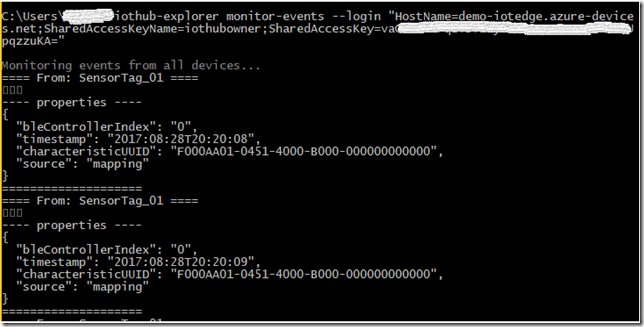
From above, the --- properties ---- is the actual raw telemetry sent by the Sensor Tag to the Pi. This is the raw data and not in JSON format and there is no actual temperature data. The UUID is for temperature signature. More on this later if I am able to discover details on the code base as to how we can fix this to send well formed JSON. Again I will update the Conclusion section to provide the solution in a later blog.
Connecting this telemetry output to do Hot Path/Warm Path/Cold Path analytics
Let me quickly define each of these IoT Analytics approaches:
- Hot Path: As messages coming to IoT Hub, you want to perform your analytics as quickly as possible since these are time sensitive scenarios. That means resources with higher cost to get the quickest results is acceptable.
- Warm Path: As messages coming to IoT Hub, you want to perform your analytics soon enough that a business defined delay or lag in determining the results is acceptable. That means resources with moderate cost to get the results in business defined time lag is acceptable.
- Cold Path: You want to perform your analytics with historical data to derive insights. That means resources with lowest cost to derive the insights is acceptable.
My narrative here is to distinguish each analytics approach in the IoT pipe-line. Your definition may differ.
Lets review how we can begin to approach Hot Path analytics such that we can visualize the data real time in a visualization tool. Following an existing article guidance Visualize real-time sensor data from Azure IoT Hub using Power BI, lets create necessary resources, like wise here I am sharing the results under each sections from the article.
Add a consumer group to your IoT hub
![clip_image001[1]](https://blogger.googleusercontent.com/img/b/R29vZ2xl/AVvXsEj5LqHq-0U8zPAM_-T47max5EQaaaeLURIvoI9ylm6FpT7xXPCzNq538D2Ai58oYspwAUD7hbTv5Q2Ex3Ejq6mmW-8-uxRhuEjJA2Rppa9u9J-JnIGLJrN8hmDZxYP2Sl92ArAovuGLy38C//?imgmax=800 "clip_image001[1]")
Create a Stream Analytics job

Add an input to the Stream Analytics job
![clip_image001[3]](https://blogger.googleusercontent.com/img/b/R29vZ2xl/AVvXsEjwV5OHOvJA-evMR4HF-dpsXroC_XQ5SMpXq-AkqQgqSQcT2J6RHJChfrfgeBevnI-pvW53cSq5A4RHB3sM_1CJind-hfOFT-KBJadioKR9inLnIR9OPCpvklCYYPSyE49KqQEcBr7mLuSX//?imgmax=800 "clip_image001[3]")
![clip_image001[5]](https://blogger.googleusercontent.com/img/b/R29vZ2xl/AVvXsEguMDPdR6A80qvQdBUkeJI-mRCpRyp9CdLUF5Ej_biNo0PKbXaLZhvC5KJE0W1qjtUF0SZjsFOR1Onx0Y7p7gwZ_3EHMOFAVoLPVo3Tw6QR8aDb0hcT7hyJWLbDrJgMKrJlRQkji1ZdDzrp//?imgmax=800 "clip_image001[5]")
Add an output to the Stream Analytics job
![clip_image001[7]](https://blogger.googleusercontent.com/img/b/R29vZ2xl/AVvXsEj_l392V4VdPeY7ENH_RRrbI4OML9p0WOhnx1FnRxLVfzIw_p6AVhtRHJeezgizBhxQd0b5Tt1ueIZ8yDGe2UFPufzpGjJIHIfeM_0phcc04rYlKDqs-9g8HNJFTNdD87JKyYjskxh-y4cj//?imgmax=800 "clip_image001[7]")


Run the Stream Analytics job

Now as you will notice there is a warning sign from the input that we created, lets further explore that by click on the input.

The warning clearly states the issue. Like mentioned in the Part I blog, the messages that are sent to Iot Hub are not in JSON format.

Lets take this how we can resolve this and follow the Conclusion section. Again I will update the Conclusion section to provide the solution in a later blog.
Connecting additional SensorTags to the same Raspberry Pi IoT Edge Gateway
The fundamental idea of a Gateway concept in IoT Scenarios is that the device or a thing that plays the role of Gateway is that it can connect to many things and play a role of gate keeper to talk further with the Cloud. In Part I we connected a single SensorTag. Here lets explore how we can connect a second SensorTag device.
I had bunch of old SensorTag CC2541, these are 1st generation and no more sold. But for the purpose of this experiment, this works.

First lets ensure that you are not running the IoT Edge, otherwise stop the run.
From the Pi SSH session, lets initiate Bluetooth shell and try connect this 2nd sensor tag and find out the MAC address:

Lets Power On the 2nd sensor tag


Note the MAC 78:A5:04:8C:13:98
Enter scan off to stop.

Now lets connect to this SensorTag in our bluetooth shell

Lets disconnect from the device using the disconnect command and then exit from the bluetooth shell using the quit command:


Now lets add the 2nd SensorTag device to the IoT Hub. Navigate to Azure Portal and to your IoT Hub, Device Explorer and add new sensor tag and make note of the new Primary Key for the SensorTag_02.

Now lets take the original sensor tag sample configuration file, lets rename that to gateway_Sensor1.json and test to ensure the configuration works

Take the gateway_Sensor1.json file and copy to gateway_Sensor2.json. Then lets update the MAC address for the sensor two and save.


Now run the gateway for Sensor 2 to test and ensure the sensor two works, make sure you have the sensor two powered on before the run:

Now lets create a 3rd configuration file that will have both sensors. Copy the Sensor1 file to gateway_Extend.json. Add the 2nd SensorTag device in the configuration file via nano editor from your SSH session:

Locate the Mapping section, notice that under the args where we had our first Sensortag entered, I have comma separated and added our second sensor tag with respective MAC and Primary Key for the deviceKey.

Next locate the below section

Copy and paste an existing section of the “controller_index along with the instructions separated by comma (like curser green highlight below. Update the controller_index with 1 and replace the respective MAC address.


Save the configuration Ctl+O and exit Ctl+X. Lets copy the content of the file and test to ensure the JSON is welformed. I used
https://jsonformatter.curiousconcept.com/ to test.
Now run the IoT Edge Gateway from the Pi. From the bellow error message, it looks like even thought the configuration is well formed JSON, the JSON parsing modules are not able to read appropriate configfuration sections where we extended with the second BLE controller.

Again I will update the Conclusion section to provide the solution in a later blog.
Conclusion
So in conclusion, I am expecting to find out more clarity on the SDK and being able to perform above tasks of correcting the Telemetry message so that it is a well formed JSON and that I can add more than one SensorTag and run a successful IoT Edge.
As I discover more clarity I will update here for next set of blogs to shed some light on these topics.


![clip_image001[4]](https://blogger.googleusercontent.com/img/b/R29vZ2xl/AVvXsEg15CyWH67uEZFkrr0Ngsnt-7r7a-eVeUBB0a2K1LOQNskNSyYhKURZPnzbB2FUDFgWTEnMNBz7Xk1bPl7bRgqLwUCzaZixh_tmwNZJfuUglDmWNdh2kfAGiyAib5Qf-0pVaMnlCRjgnIWq//?imgmax=800 "clip_image001[4]")
![clip_image002[4]](https://blogger.googleusercontent.com/img/b/R29vZ2xl/AVvXsEi0zeLo2CLSsWWk71GaHXF8zZsO2D-AUEbwQECfy9ntKzNVi8OkiAZN5SiSIsdNDouLZRhCN0MgaFjUDTntX4EGXrnhEWAgJ4LlDNois5FoLf3Ks-oBwNhQilLAMk2HL37eiHk234p46Bbm//?imgmax=800 "clip_image002[4]")


